File:PedalPCB Resistor Color Code Chart.png and Main Page: Difference between pages
(Difference between pages)
Jump to navigation
Jump to search
No edit summary |
|||
| Line 1: | Line 1: | ||
PedalPCB Resistor Color Code Chart | This is the testing area for the '''PedalPCB Wiki'''. The information listed here is for experimental purposes only. | ||
== Component References == | |||
* [[Potentiometers]] | |||
* [[LEDs]] | |||
* [[Jacks]] | |||
* [[Switches]] | |||
** [[Momentary vs Latching]] | |||
** [[Normally Open vs Normally Closed]] | |||
** [[Make before Break vs Break before Make]] | |||
** [[ON/ON]] | |||
** [[ON/OFF/ON]] | |||
** [[ON/ON/ON]] | |||
** [[SPST]] | |||
** [[SPDT]] | |||
** [[DPDT]] | |||
** [[3PDT]] | |||
** [[4PDT]] | |||
** [[Rotary Switches]] | |||
* [[SMD Component Lookup]] | |||
* [[EIA-96 SMD Resistor Codes]] | |||
* [[Op Amp Slew Rates]] | |||
* [[Resistor Color Code Chart]] | |||
== Wiring Diagrams == | |||
* [[Standard True-Bypass Wiring]] | |||
* [[2-in-1 Pedal Wiring]] | |||
* [[2-in-1 Pedal Wiring (Single Footswitch)]] | |||
* [[2-in-1 Pedal Wiring (AB)]] | |||
* [[3PDT Order Switch Wiring]] | |||
* [[Expression Control Wiring]] | |||
* [[DPDT ON/ON/ON as 3-way Switch]] | |||
== To Do == | |||
* Basic Electronics Theory | |||
* Resistors | |||
* Capacitors | |||
* Diodes | |||
* Transistors | |||
* Integrated Circuits | |||
* Enclosures | |||
* Switches | |||
* [[PCB list by SKU]] | |||
* [[JFET chart]] | |||
Revision as of 16:46, 6 January 2023
This is the testing area for the PedalPCB Wiki. The information listed here is for experimental purposes only.
Component References
- Potentiometers
- LEDs
- Jacks
- Switches
- SMD Component Lookup
- EIA-96 SMD Resistor Codes
- Op Amp Slew Rates
- Resistor Color Code Chart
Wiring Diagrams
- Standard True-Bypass Wiring
- 2-in-1 Pedal Wiring
- 2-in-1 Pedal Wiring (Single Footswitch)
- 2-in-1 Pedal Wiring (AB)
- 3PDT Order Switch Wiring
- Expression Control Wiring
- DPDT ON/ON/ON as 3-way Switch
To Do
- Basic Electronics Theory
- Resistors
- Capacitors
- Diodes
- Transistors
- Integrated Circuits
- Enclosures
- Switches
- PCB list by SKU
- JFET chart
File history
Click on a date/time to view the file as it appeared at that time.
| Date/Time | Thumbnail | Dimensions | User | Comment | |
|---|---|---|---|---|---|
| current | 16:26, 6 January 2023 | 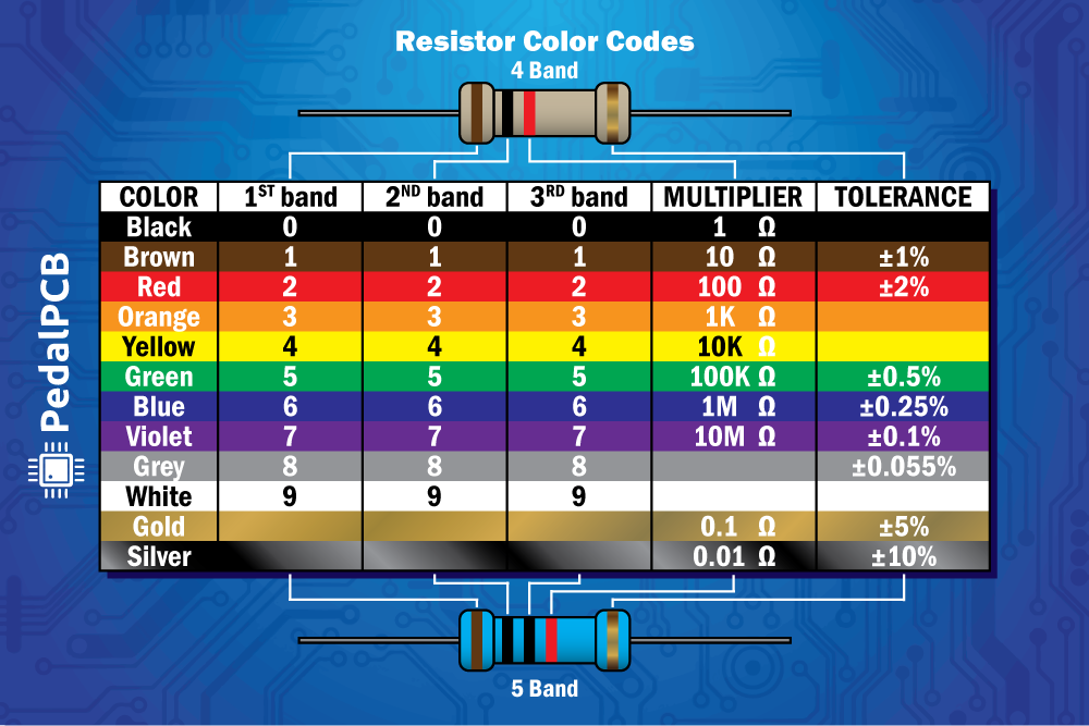 | 1,000 × 667 (194 KB) | PedalPCB (talk | contribs) |
You cannot overwrite this file.
File usage
The following page uses this file: