Potentiometers
Potentiometers
Most PedalPCB boards are designed for use with 16mm right-angle pin PCB mounted potentiometers.


Pin Designation
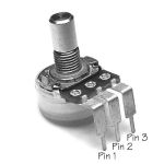
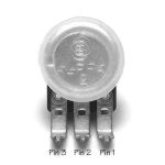
Pin 1 of a potentiometer is defined as the left-most pin when looking at the potentiometer with the shaft facing you.
Installation
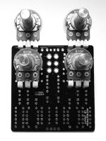
Unless otherwise noted in the specific project documentation, potentiometers (except trim pots) should be installed on the back side of the PCB (opposite of components). Pin 1 of the potentiometer should be installed into the square pad on the PCB. Potentiometers will extend towards the top of the enclosure, and typically the top row of potentiometers will fit underneath the top mounted 1/4" jacks.
Dust Caps
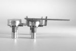
Potentiometers installed underneath the PCB should be insulated with dust caps or some other insulating material to prevent contact with the back of the PCB.
Taper
Potentiometer taper is indicated by a letter prefix before the value. (eg: B50K would indicate a 50K Linear taper potentiometer)
A - Logarithmic (Audio) Taper
B - Linear Taper
C - Anti-Logarithmic (Reverse Log) Taper
W - W-Taper
W-taper is log taper for the first 50% of rotation, then reverse-log for the last 50% of rotation. These are typically used in tone control circuits.
G - G-Taper
G-taper is the opposite of W-taper. The taper is reverse-log for the first 50% of rotation, then log for the last 50% of rotation. These are primarily seen in Boss pedals.